Lesson 7 (CC2 level)
Not to be confused with Lesson 7.
Lesson 7 is the 71st level in Chip's Challenge 2. It is also the last lesson level. It was created by Chuck Sommerville.

| |
| Level set | Chip's Challenge 2 |
|---|---|
| Level number | 71 |
| Designer | Chuck Sommerville |
| Hint | (See "Hints" section) |
| Chips | 0 required / 0 available |
| Time limit | 0 |
| Steam (Scores) | |
| Bold time | 0 |
| Public time | 0 |
| Casual difficulty | ***** |
| Bold execution difficulty |
***** |
| Bold routing difficulty |
***** |
| Bold luck difficulty |
***** |
| Bold score | 35500 |
| Public score | 35500 |
| Casual difficulty | ***** |
| Bold execution difficulty |
***** |
| Bold routing difficulty |
***** |
| Bold luck difficulty |
***** |
Full level map
Hints
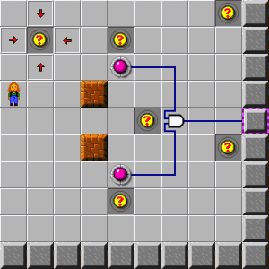
- Be sure to read all the clues carefully. This may seem easy, but it gets complicated.
- This is an 'and' gate. Both of its inputs must be on for its output to be on.
- This button controls one of the inputs to the 'and' gate. It needs to be pressed to be on.
- This door is connected to the output of the 'and' gate. It will open when its input is on.
- Push the blocks onto the two buttons.
- This is an inverter. When its input is on, its output is off. When its input if off, its output is on.
- This black button controls the input to the inverter. It is normally on. It needs to be pressed to be off.
- This door is connected to the output of the inverter. It will open when its input is on.
- Push the block onto the button.
- This is an 'or' gate. When either of its inputs is on, its output is on.
- This button controls one of the inputs to the 'or' gate. It needs to be pressed to be on.
- This door is connected to the output of the 'or' gate. It will open when its input is on.
- Push the block onto one of the buttons.
- This is a 'nand' gate. 'nand' stands for 'not and'.
- This button controls one of the inputs to the 'nand' gate. It needs to be pressed to be on.
- Both of its inputs must be on for its output to be off.
- This door is connected to the output of the 'nand' gate. It will open when its input is off.
- Push the blocks onto the two buttons.
- This is the 'xor' gate. xor stands for exclusive-or.
- Its output is on when one and only one of its inputs is on.
- This is one of the inputs to the 'xor' gate.
- This door is connected to the output of the 'xor' gate. It will open when its input is off.
- Either push the top block off or push the bottom block on.
- This is the 'latch' gate. It has a capture input, a data input, and an output.
- This is the capture input to the latch.
- When it is on the output will be the same as the data on the other input.
- When it is off, the output stays the same as it was the last time the capture was on.
- This is the data input to the latch gate.
- The state of this input is captured by the capture input above.
- This door is connected to the output of the 'latch' gate. It will open when its input is on.
- Push the block onto the bottom button, then step on the top button.
- This is a counter gate. It is using its increment input and its overflow output.
- This is the increment input to the counter gate.
- When its input goes from off to on, it will count up by one.
- When the counter goes from 9 to 0, it will send a quick pulse out the overflow output. A pulse is a short 'on' signal.
- This door is connected to the overflow output of the counter. It toggles when its input goes from off to on.
- Step on the button until the number says 0.
- This counter gate is using its decrement input, and its underflow output.
- This is the decrement input to the counter.
- When it goes from off to on, the counter will count down by one.
- This door is connected to the underflow output of the counter.
- When the counter reaches 9, the underflow output will turn on and open this door.
- Step on the button until the number says 9.
| Previous Level | Current Level | Next Level |
|---|---|---|
| ← Rail Bowling | Lesson 7 (CC2 level) | On and Off → |